Pipe Stress | Flexibility | Support Engineering

Piping Stress & Flexibility Analysis

Pipe stress, support, flexibility and equipment load analysis for industrial piping systems, with practical recommendations for code compliance, constructability and safe operation.

CAESAR IIAutoPIPEASME B31.3Nozzle Loads

Service overview

Practical stress engineering for safe piping systems.

COC Engineering evaluates piping systems for thermal expansion, sustained loads, occasional loads, support reactions and equipment nozzle loads.

The objective is to confirm code compliance while keeping the layout constructable, maintainable and aligned with project specifications.

B31ASME code-based checks
15Reference pictures included unchanged
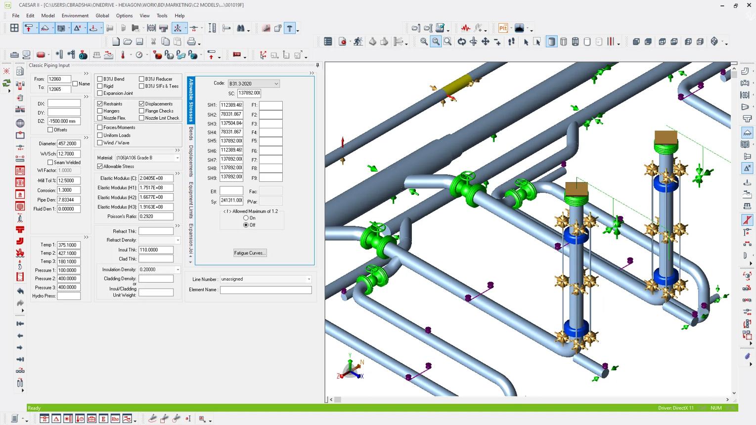
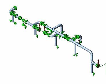
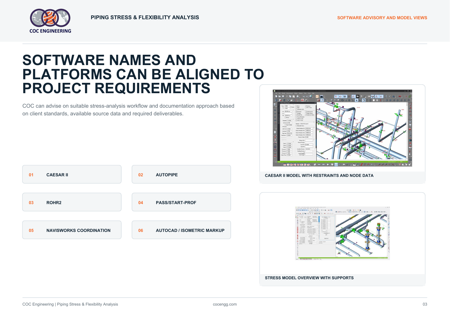
CAESAR II software model screenshot

Engineering support

Stress checks that support design, review and construction.

The service links stress modelling, support engineering, load-case review and equipment interface checks into a controlled engineering workflow.

  • Static stress and flexibility analysis
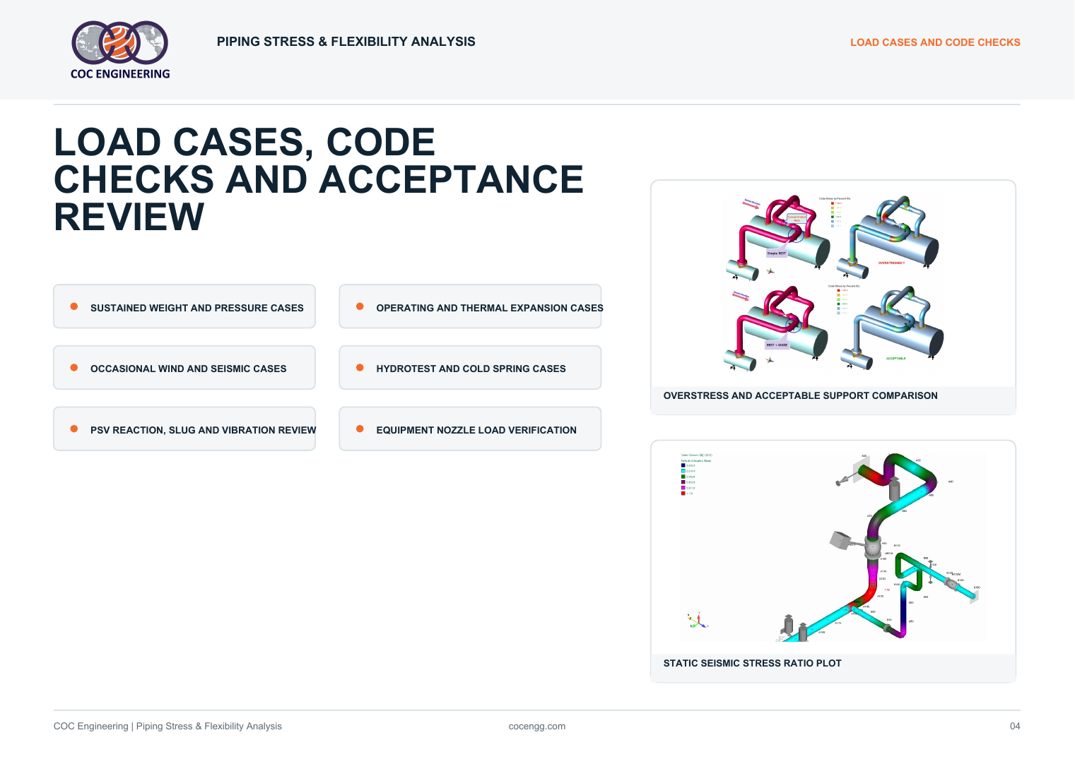
  • Sustained, expansion, occasional and hydrotest cases
  • Equipment nozzle load verification
  • Pipe support, guide, anchor and spring support review
  • Marked-up isometrics, load summaries and calculation reports

Capabilities

Piping stress analysis scope

Complete stress support for process, utility and critical piping systems.

01

Piping Stress Analysis

Static stress, flexibility and displacement checks for process and utility piping.
02

Code Compliance

ASME B31.3, ASME B31.1 and project specification load-case verification.

03

Support Engineering

Pipe supports, spring supports, anchors, guides, stops and restraint optimization.

04

Equipment Loads

Nozzle load checks for pumps, compressors, vessels, tanks and heat exchangers.

05

Dynamic Review

Wind, seismic, PSV reaction, slug, vibration and occasional loading review.

06

Reporting

Stress reports, marked-up isometrics, support loads and action registers.

Software advisory

Software names and platforms can be aligned to project requirements.

COC can advise on the suitable stress-analysis workflow and documentation approach based on client standards, available source data and required deliverables.

01CAESAR II
02AutoPIPE
03ROHR2
04PASS/START-PROF
05Navisworks coordination
06AutoCAD / isometric markup

Reference pictures

Clear stress-analysis pictures used unchanged

All supplied pictures are displayed without cropping, stretching, dark overlays or visual edits.
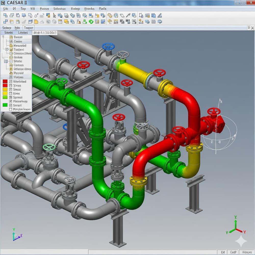
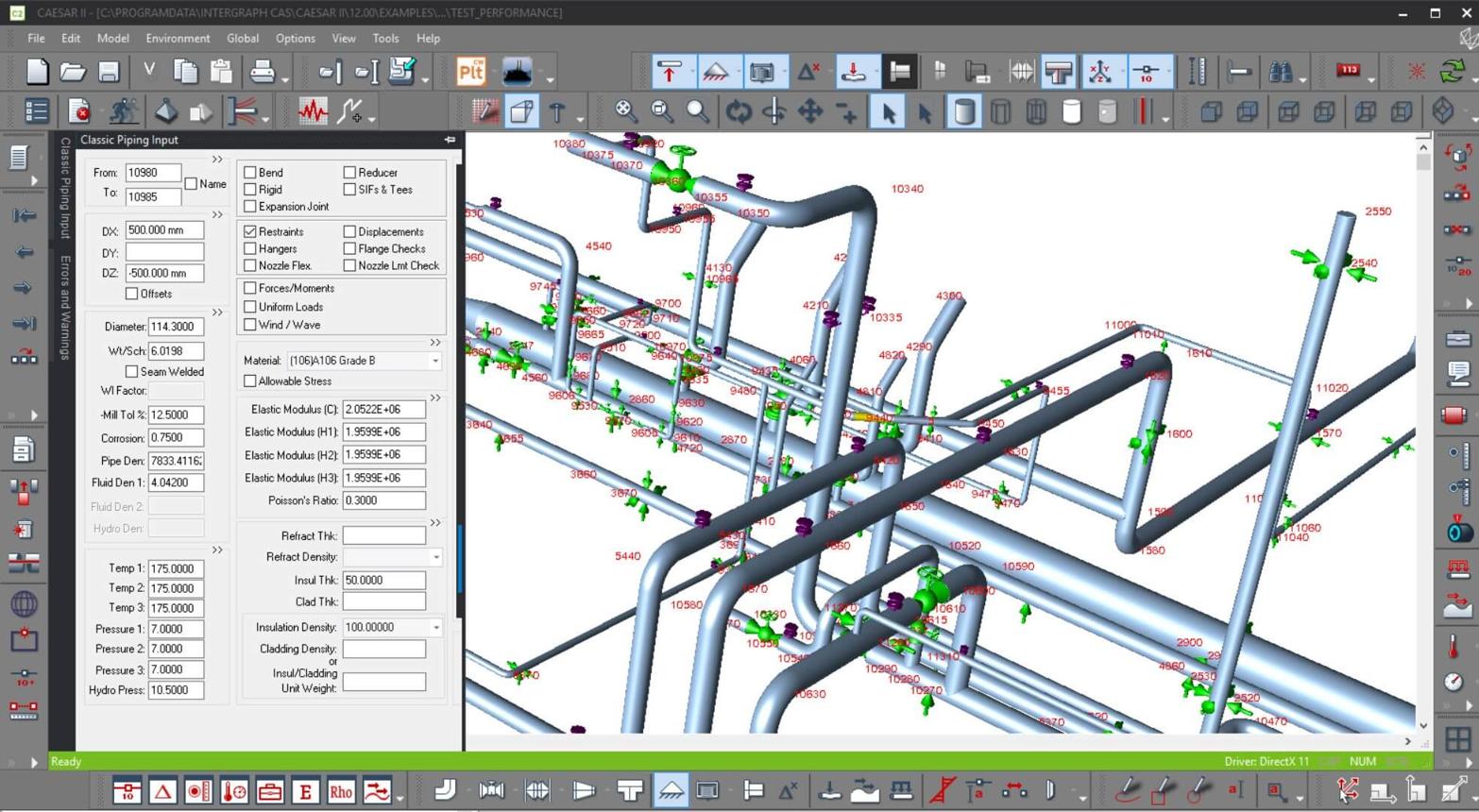
CAESAR II model input and piping stress review
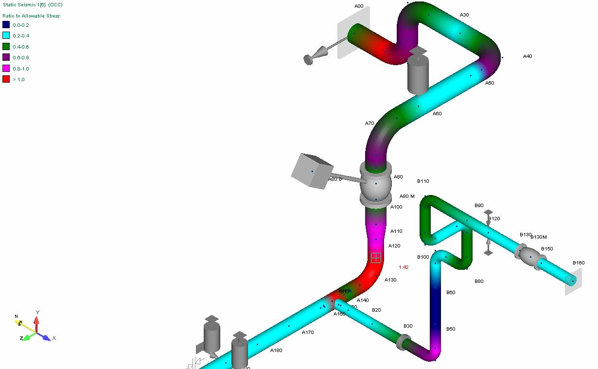
Stress ratio colour plot on routed piping
CAESAR II piping model and restraint input view
Stress software model overview
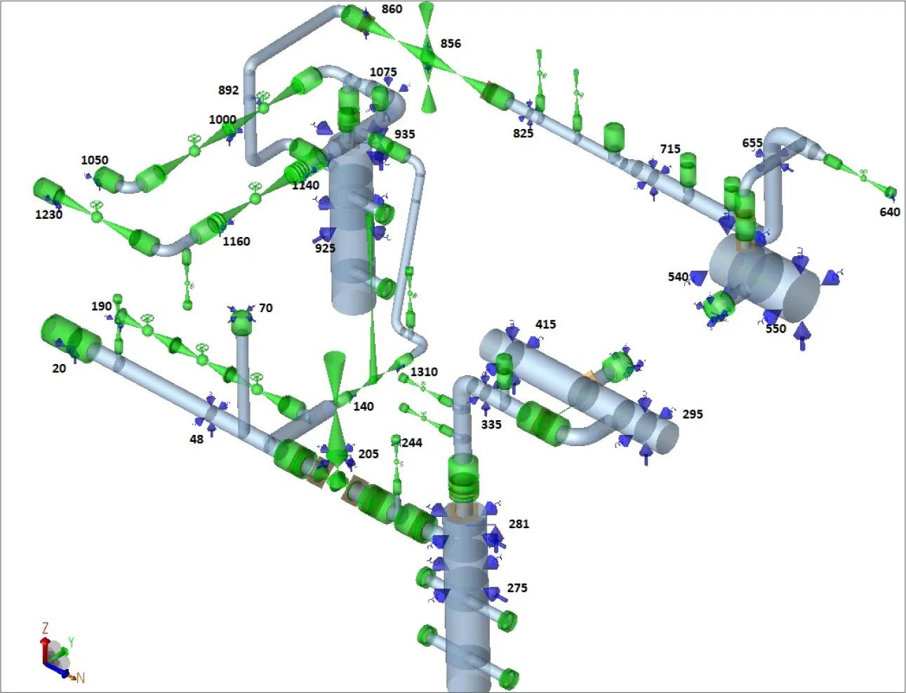
Piping system with support and node locations
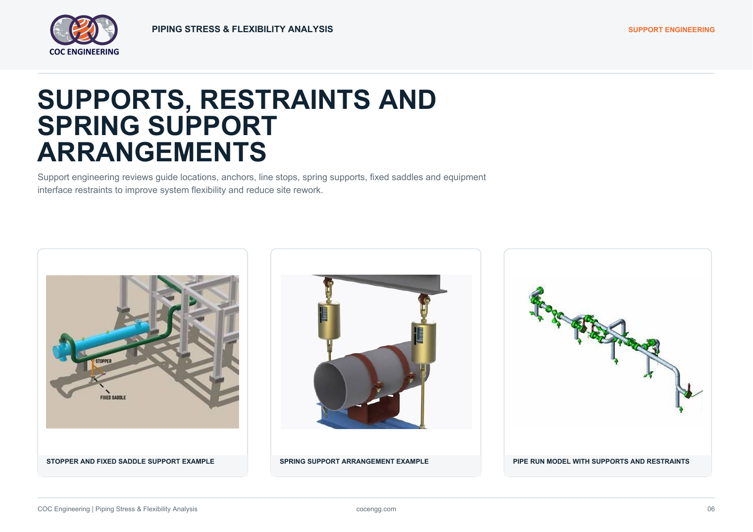
Pipe run model with supports and restraints
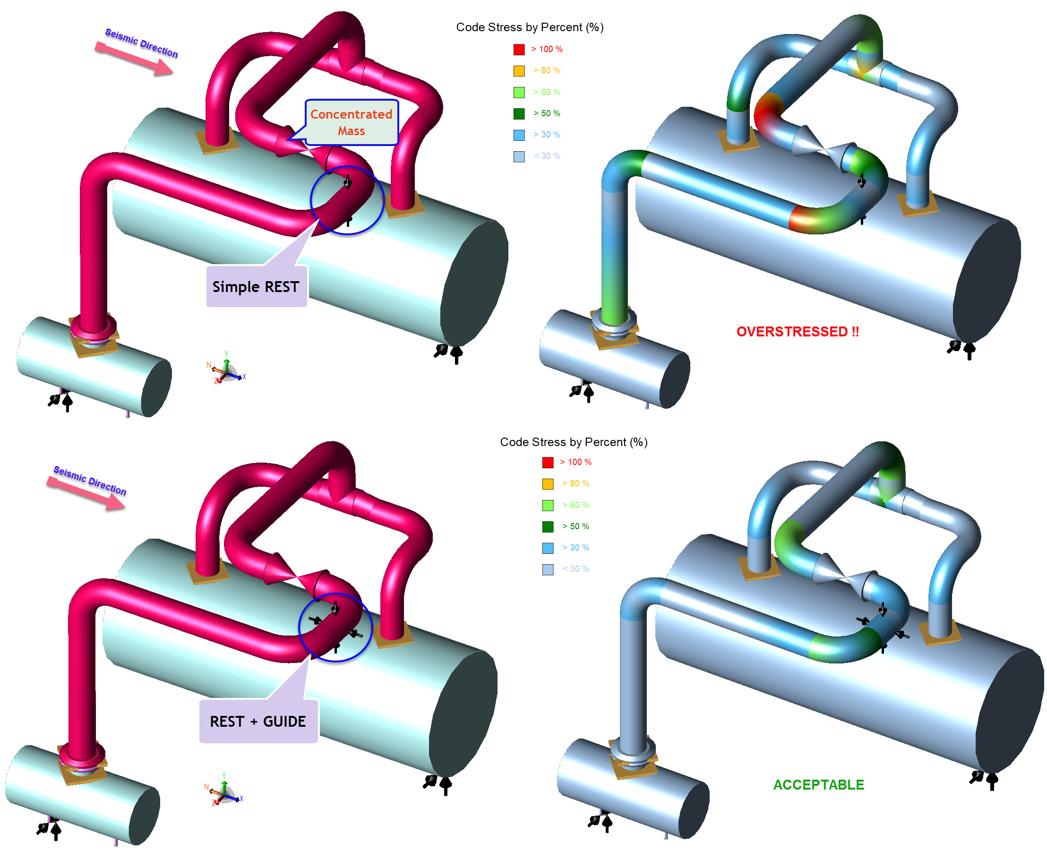
Overstress and acceptable support comparison
Static seismic stress ratio plot
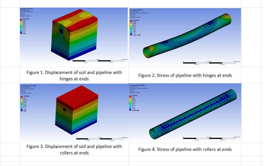
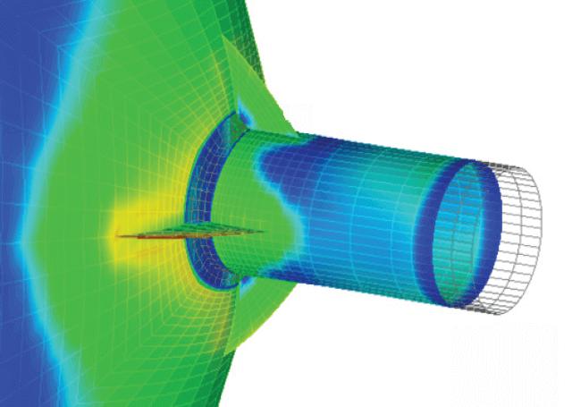
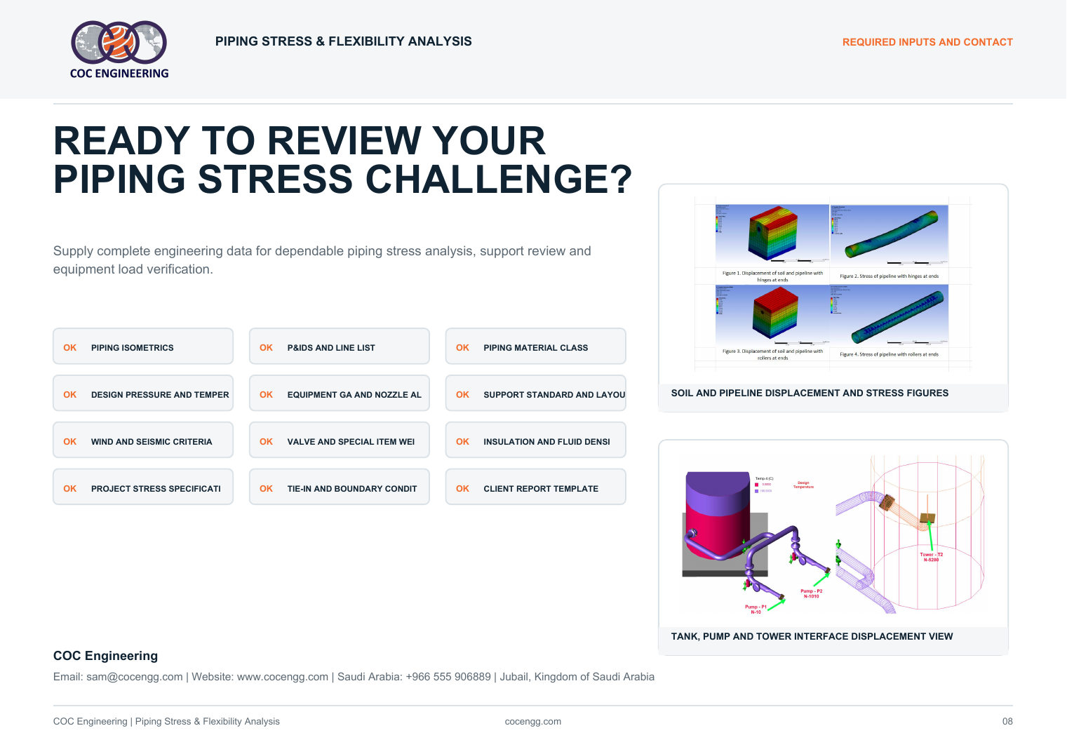
Soil and pipeline displacement and stress figures
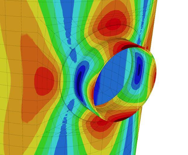
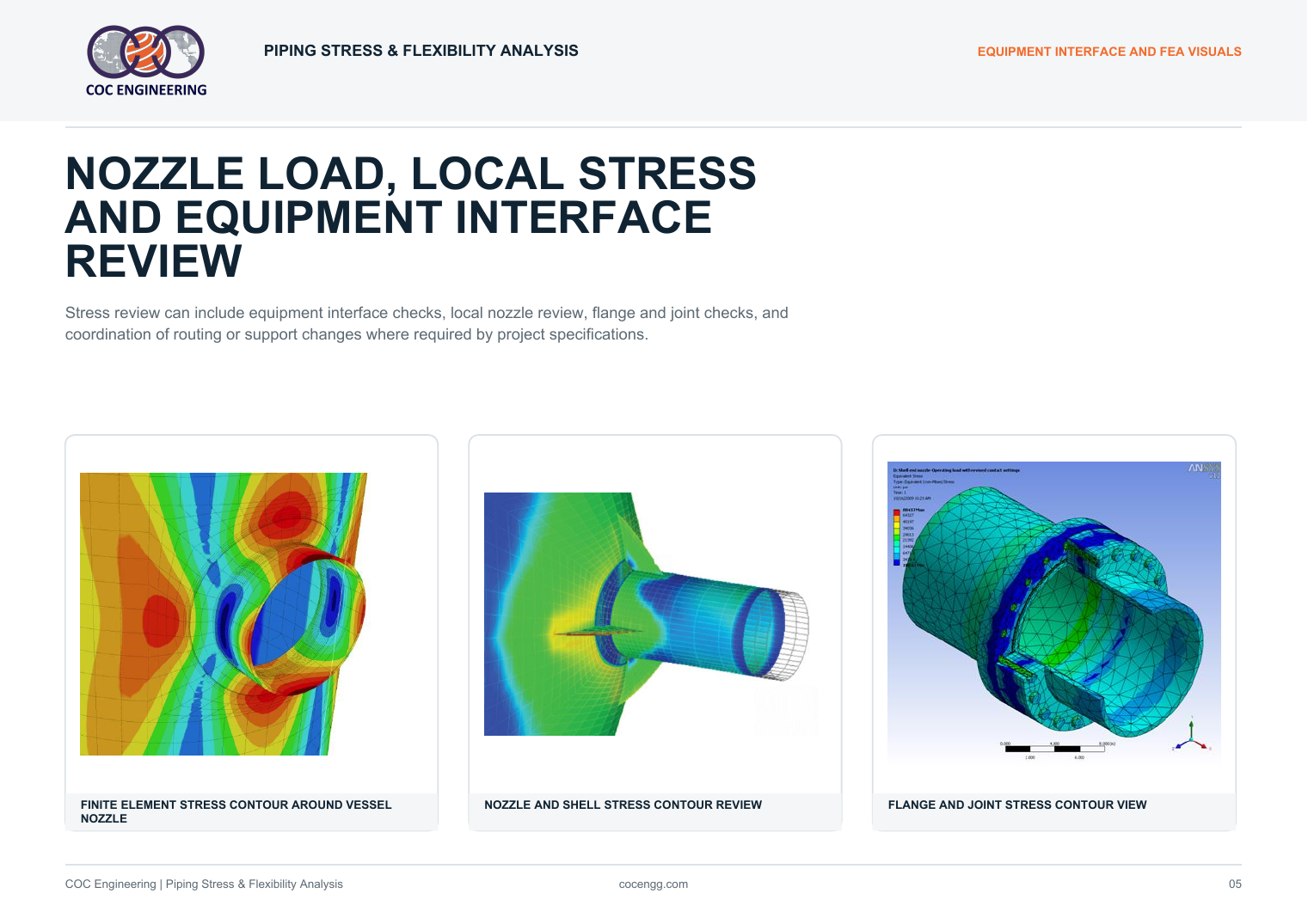
Finite element stress contour around vessel nozzle
Nozzle and shell stress contour review
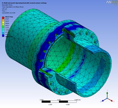
Flange and joint stress contour view
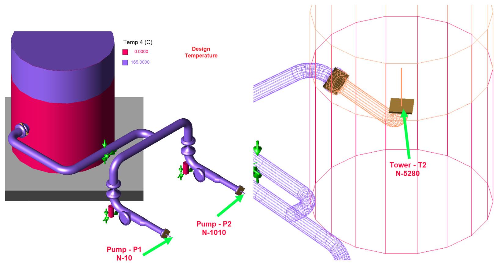
Tank, pump and tower interface displacement view
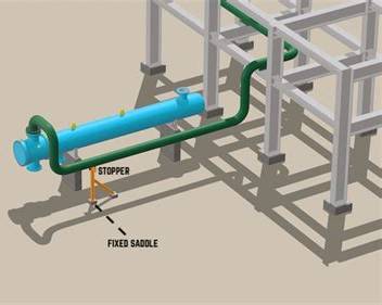
Stopper and fixed saddle support example
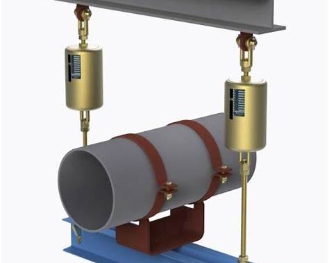
Spring support arrangement example

Deliverables

Reports and markups for design approval.

Deliverables can be formatted to client templates and project specifications with clear notes for routing changes, support changes and equipment interface actions.

01Stress calculation report
02Stress model files
03Stress isometric markups
04Support load summary
05Nozzle load report
06Spring support selection data
07Expansion loop recommendations
08Action register

Workflow

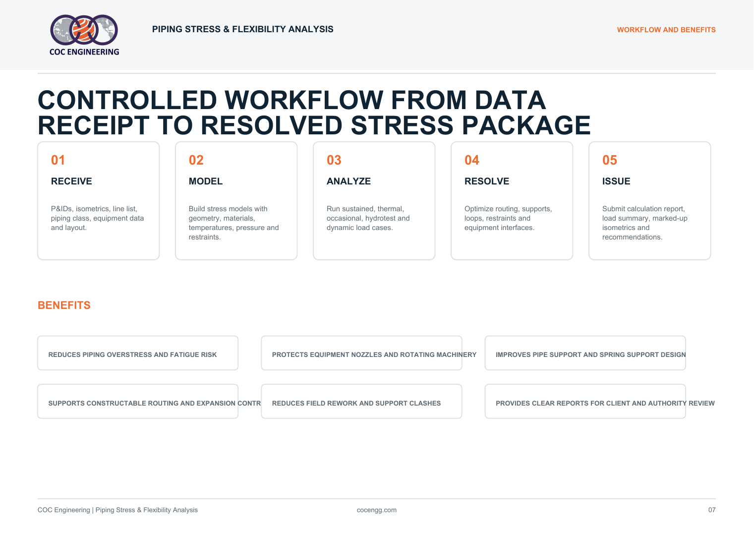
Controlled workflow from data receipt to resolved stress package.

Analysis proceeds from project source data to model, load cases, recommendations and final report issue.

01

Receive

P&IDs, isometrics, line list, piping class, equipment data and layout.

02

Model

Build stress models with geometry, materials, temperatures, pressure and restraints.

03

Analyze

Run sustained, thermal, occasional, hydrotest and dynamic load cases.

04

Resolve

Optimize routing, supports, loops, restraints and equipment interfaces.

05

Issue

Submit calculation report, load summary, marked-up isometrics and recommendations.

Benefits

Improve piping reliability and reduce site rework.

Stress analysis helps protect piping, equipment, supports and project schedules.

Overstress control

Reduces piping overstress, displacement and fatigue risk.

Nozzle protection

Supports equipment nozzle and rotating machinery load checks.

Support clarity

Improves support, guide, anchor and spring support decisions.

Constructability

Helps reduce field rework, clashes and late routing changes.

Industries

Stress support for demanding industrial systems.

Applicable to new projects, modifications, brownfield tie-ins and plant improvement work.

Oil & Gas
Petrochemical
Power Generation
Water & Utilities
Mining
Industrial Plants

Required inputs

Ready to review your piping stress challenge?

Supply complete engineering data for dependable piping stress analysis, support review and equipment load verification.

OKPiping isometrics
OKP&IDs and line list
OKPiping material class
OKDesign pressure and temperature
OKEquipment nozzle allowables
OKSupport standard and layout
OKWind and seismic criteria
OKProject stress specification

Bulletin visuals

Piping Stress & Flexibility Analysis bulletin

The regenerated bulletin uses a light page background throughout and includes the supplied stress-analysis pictures.
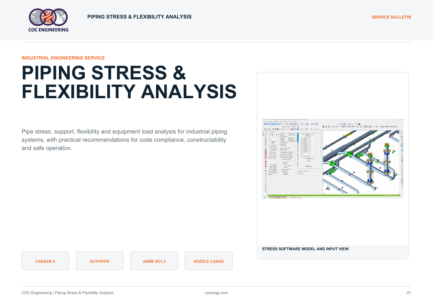
Piping Stress and Flexibility Analysis bulletin page 1
Cover and service snapshot
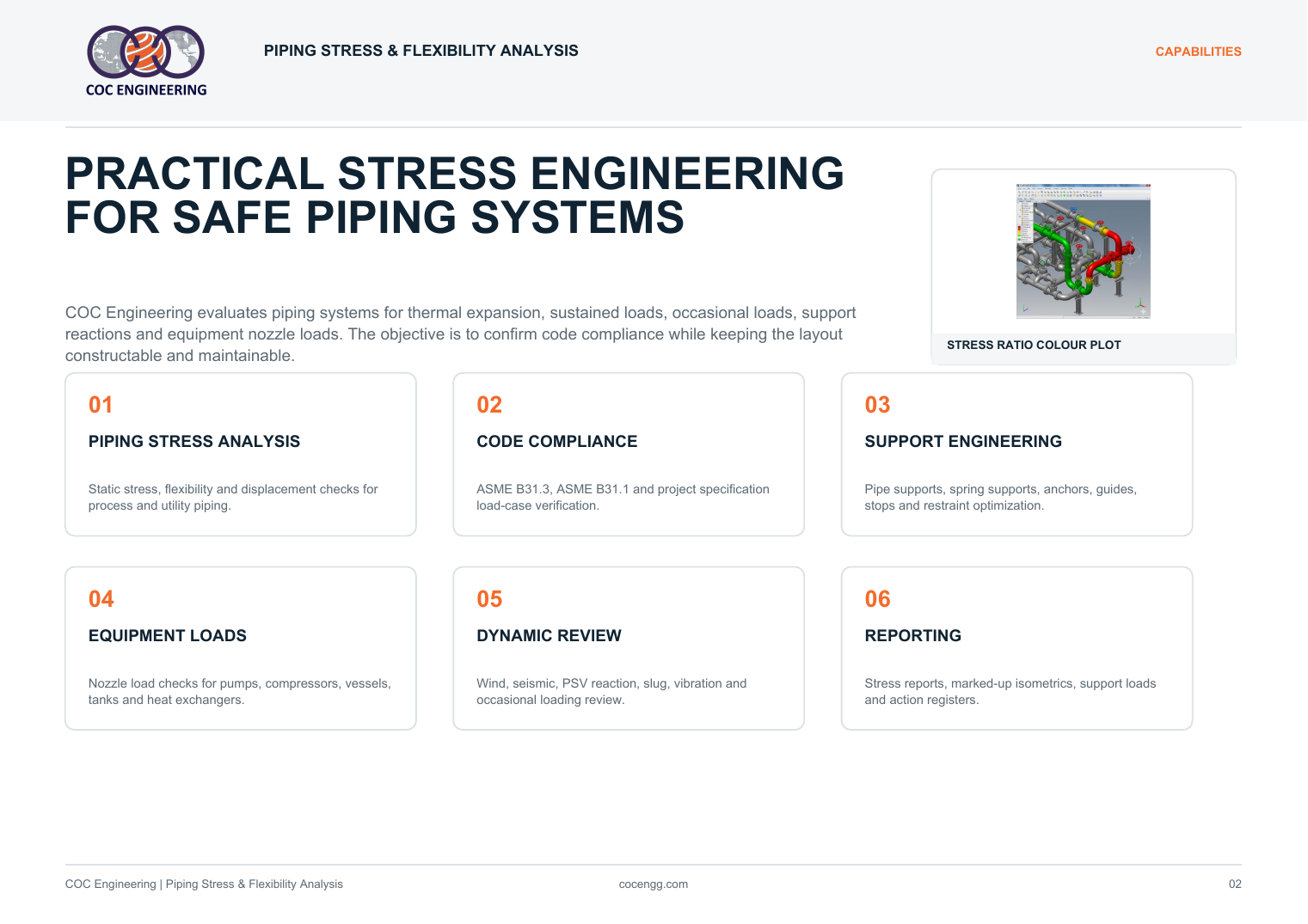
Piping Stress and Flexibility Analysis bulletin page 2
Capabilities and overview
Piping Stress and Flexibility Analysis bulletin page 3
Software advisory and model views
Piping Stress and Flexibility Analysis bulletin page 4
Load cases and code checks
Piping Stress and Flexibility Analysis bulletin page 5
Equipment interface and FEA visuals
Piping Stress and Flexibility Analysis bulletin page 6
Support engineering visuals
Piping Stress and Flexibility Analysis bulletin page 7
Workflow and benefits
Piping Stress and Flexibility Analysis bulletin page 8
Required inputs and contact

Project or review package in mind?

Let us build the right stress engineering response.

Contact our team
WA